Guide to design of Doubly reinforced Sections | Civil Engineering

What are Doubly reinforced sections?

Sections that have tensile as well as compressive reinforcement are called doubly reinforced sections.

Necessity of design of doubly reinforced sections

When the dimensions of the beam are restricted for architectural or structural considerations, the section has insufficient area of concrete which results in inability of the beam to take sufficient compressive stresses. If not paid attention to, it could result in structural failure.

To solve this problem, steel is placed in the compressive area of the section to help the concrete section in resisting compressive stresses. (Steel is good at taking up both compression and tension.)

In this way, the moment of resistance of the section is increased without altering its dimensions.

Three important conditions where doubly reinforced sections are to be used:

1)       When the dimensions of the beam are restricted for architectural or structural purposes.

2)       Sections that are subjected to the reversal of bending moment (piles, braces in water towers etc.

3)       The portion of the beam over middle support in continuous T beams has to be designed as doubly reinforced section.

We are now going to begin with a series of articles on “Design of Doubly reinforced sections”. In our previous series of articles for “Singly reinforced sections“, we have covered every step in detail for the design and analysis of Singly reinforced sections.

We would be covering the following for “Doubly reinforced Sections”:

What are doubly reinforced sections?

Methods for determining Neutral Axis?

Solved numerical examples for determining Neutral Axis

Numerical examples for practice (Find Neutral axis)

Methods for calculating Moment of Resistance

Numerical example for calculating Moment of resistance

Types of problems in Doubly reinforced sections

Determining stresses in steel and concrete 

Numerical example | Stresses in steel and concrete

So let us begin with understanding the methods for determining the neutral axis for doubly reinforced sections.

Methods of determining Neutral axis for doubly reinforced sections

METHOD ONE:

Given that:

Dimensions of the beam:

b = width of the beam, d = depth of the beam

Permissible stresses in concrete = σcbc

Permissible stress in steel = σst

Modular ratio = m

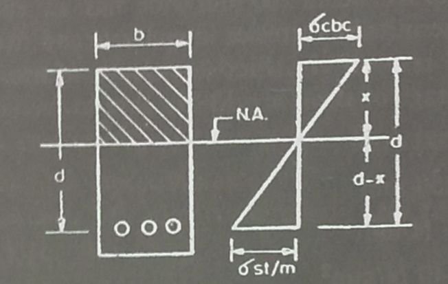
From similar triangles in the equivalent concrete stress diagram,

σcbc/ (σst/m) = xc/(d – xc)

Read more

Green Electric Components | LED Lights | Research in lighting

Future of Lighting Industry

We are all acquainted with LED (light emitting diode). It is a semiconductor light source and was introduced as a practical electronic component in 1962. Earlier, LEDs emitted low-intensity red light but now the scenario has completely changed. We can now count LEDs under GREEN electronic component. They are tiny but efficient. Technology has made it possible in achieving efficiency with LED lighting.

LEDs (Light emitting diode)

LEDs pros and cons

Let us first look at it with a positive perspective.

LEDs are supposed to be the future of our lighting industry. They require low power for illumination. The power required for illumination is as low as required for a flashlight or the screen of our cellphone.

LEDs are very useful to light up smaller rooms. Bright white light can be achieved with minimum requirement of electric power. It has been used by the lighting designers. They can be very easily integrated with the false ceiling in any mall or showroom. Since, the requirement for the number of lights is larger in a showroom, LEDs are a very superior and an economical alternative since they are efficient and at the same time consume less electric power. I would say this is great way to embrace sustainability.

Now, let’s look at it with a perspective that will help us understand the shortcomings in LEDs technology. We will also discuss how researchers have found a perfect way to overcome these shortcomings.

Read more

New Concept of Modern Bathrooms

To say that bath spaces have changes would be an understatement. The enormous sophistication in the range of bath products and the change in the way people look at the space, has attracted several international players into the Indian markets, witha slew of technologically advanced and designed products.

New concept of Modern Bathrooms

The new trendy bathroom designs are making use of lot of wood furniture into the bathroom. Various companies are into the race for designing the furniture specifically for the application area and is resistant to both water and humidity.

Wood surfaces act as a link between the bathroom as a space and its diverse range of elements. When fitted with panelling, drawers or shelves, washbasin, bathtubs and shower trays become items of furniture in their own right. These elements can also be complemented by wall cabinets with valuable storage space, bathrooms are currently in a period of transition.

Read more

Guide to design of Singly reinforced beams | Solved examples

Singly reinforced beams | Building Construction

For design of “Singly reinforced beam” article series, we have covered the following:

Now we will move on with another solved example where we will calculate the Moment of resistance and determine the position of the Neutral axis. For this we will have to use the formulas that we have derived earlier in our previous articles in the list above.

Numerical Problem

Calculate the moment of resistance of an RC beam 250x550mm overall. Reinforcement is 1521mm2 and is placed at a distance of 25mm from the bottom.

cbc = 7N/mm2, σst = 140N/mm2, m = 13.33)

Given that:

b = breadth of a rectangular beam = 250mm

d = effective depth of a beam = 550 – 25 = 525mm

x = depth of neutral axis below the compression edge = ?

Ast = cross-sectional area of steel in tension = 1531mm2

σcbc = permissible compressive stress in concrete in bending = 7N/mm2

σst = permissible stress in steel = 140 N/mm2

m =  modular ratio = 13.33

We have to find the value for Moment of resistance. To calculate Mr, we have to first calculate NA(critical) and NA (actual).

To find Neutral axis (NA) (critical):

σcbc /(σst/m) = xc/(d – xc)

7/(140/13.33) = xc/(500 – xc)

xc = 209.969mm = 210mm

Read more

Numerical example 2 | Singly reinforced Sections

Guide to design of Singly reinforced Sections | Civil Engineering

For “Singly reinforced sections” article series, we have covered the following:


Now we will move on with our next solved example in which we will make use of formulas derived earlier. That is why it is necessary that you go through the entire step by step guide in order to gain complete understanding.

Numerical Problem

Calculate the moment of resistance of an RC beam 250mm wide, the depth of the centre of reinforcement being 500mm. Assume σcbc = 5N/mm2, σst = 140 N/mm2, modular ratio = 18.66

Given that,

b = width of the beam = 250mm

d = depth of the beam = 500mm

σcbc = permissible compressive stress in concrete in bending = 5N/mm2

σst = permissible stress in steel = 140 N/mm2

m =  modular ratio = 18.66

To find Neutral Axis (NA)

σcbc /(σst/m) = xc/(d – xc)

5/(140/18.66) = xc/(500 – xc)

Xc = 199.95mm = 200mm

Read more

Solved numerical examples | Design of Singly reinforced sections

Guide to design of Singly reinforced Sections | Building Construction

For the “design of Singly reinforced sections” article series, we have covered the following:


Now we will move on with our next solved numerical example in which we will make use of the formulas that we have derived in our earlier articles.

Numerical Problem

Determine the following:

a)      The position of the neutral axis

b)      Lever arm

c)       Moment of resistance

d)      Percentage of steel

(For a rectangular beam section of width b mm and effective depth d mm. Take σcbc = 5 N/mm2, σst = 140 N/mm2, m = 18.66

To find Neutral Axis (NA)

σcbc /(σst/m) = xc/(d – xc)

5/(140/18.66) = xc/(d – xc)

Therefore, xc  = 0.399d mm= 0.4dmm

Read more

Moment of Resistance | Design of Singly reinforced Sections

Moment of Resistance | Guide to design of Singly reinforced Sections

For the design of Singly reinforced Sections article series, we have covered the following:


Now we will move on with our discussion on “Moment of resistance” and derive the formula for Moment of resistance for balanced section, under-reinforced section and over reinforced section.

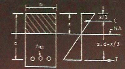
The moment of resistance of the concrete section is the moment of couple formed by the total tensile force (T) in the steel acting at the centre of gravity of reinforcement and the total compressive force (C) in the concrete acting at the centre of gravity (c.g.) of the compressive stress diagram. The moment of resistance is denoted by M.

The distance between the resultant compressive force (C) and tensile force (T) is called the lever arm, and is denoted by z.

Moment of resistance | Singly reinforced Section

From the diagram above, it is clear that the intensity of compressive stress varies from maximum at the top to zero at the neutral axis.

Therefore, centre of gravity of the compressive force is at a distance x/3 from the top edge of the section.

Therefore, z = d-x/3

Read more

Solved Numericals for Singly reinforced Sections | Design Method 2

Design of Singly reinforced Sections | Method 2

In our article series for Singly reinforced sections, we have covered the following:


Numerical Problem

Find the position of the neutral axis of a reinforced concrete beam 150mm wide and 400mm deep (effective). Area of tensile steel is 804mm2. (modular ratio = m = 18.66)

Step One:

Given that:

b = breadth of a rectangular beam = 150mm

d = effective depth of a beam = 400mm

Ast = cross-sectional area of steel in tension = 804mm2

x = depth of neutral axis below the compression edge

m = modular ratio = 18.66

Taking moments of area of compression and tension sides about neutral axis,

bx.x/2 = mAst (d – x)

Read more

Design of Singly reinforced sections | Design Method 2

Guide to design of Singly reinforced Sections

For “Singly reinforced sections” article series, we have covered the following:


Now we will move on with our discussion on “2nd Design method” for the design of Singly reinforced Sections.
We will follow a simple three-step procedure for the design of singly reinforced sections.

Step One:

Given that:

  • Dimensions of section (b and d)
  • Area of tensile steel (Ast)
  • Modular ratio (m)
Stress-strain diagram

From the figure above, we can see that the neutral axis is situated at the centre of gravity of a given section. Therefore, the moments of area on either side are equal.

Read more

Solved numericals for Singly reinforced Sections | Design Method 1

Design of Singly reinforced Sections | Method 1

In our article series for Singly reinforced sections, we have covered the following:


Numerical Problem

An RC beam 200mm wide has an effective depth of 350mm. The permissible stresses in concrete and steel are 5N/mm2 and 140 N/mm2 respectively. Find the depth of neutral axis, area of steel and percentage of steel. (modular ratio (m) = 18.66)

Step One:

Given that:

b = breadth of a rectangular beam = 200mm

d = effective depth of a beam = 350mm

x = depth of neutral axis below the compression edge = ?

Ast = cross-sectional area of steel in tension = ?

σcbc = permissible compressive stress in concrete in bending = 5N/mm2

σst = permissible stress in steel = 140 N/mm2

m = modular ratio = 18.66

From the concrete stress diagram, the formula is given as,

σcbc/(σst/m) = x/(d – x)

5/(140/18.66) = x/(350-x)

Therefore, x = 139.97mm

Read more