Guide to design of Singly reinforced beams | Solved examples

Singly reinforced beams | Building Construction

For design of “Singly reinforced beam” article series, we have covered the following:

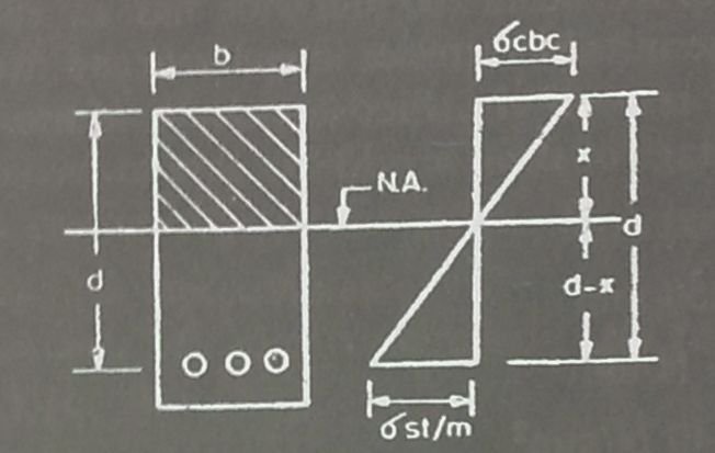
Now we will move on with another solved example where we will calculate the Moment of resistance and determine the position of the Neutral axis. For this we will have to use the formulas that we have derived earlier in our previous articles in the list above.

Numerical Problem

Calculate the moment of resistance of an RC beam 250x550mm overall. Reinforcement is 1521mm2 and is placed at a distance of 25mm from the bottom.

cbc = 7N/mm2, σst = 140N/mm2, m = 13.33)

Given that:

b = breadth of a rectangular beam = 250mm

d = effective depth of a beam = 550 – 25 = 525mm

x = depth of neutral axis below the compression edge = ?

Ast = cross-sectional area of steel in tension = 1531mm2

σcbc = permissible compressive stress in concrete in bending = 7N/mm2

σst = permissible stress in steel = 140 N/mm2

m =  modular ratio = 13.33

We have to find the value for Moment of resistance. To calculate Mr, we have to first calculate NA(critical) and NA (actual).

To find Neutral axis (NA) (critical):

σcbc /(σst/m) = xc/(d – xc)

7/(140/13.33) = xc/(500 – xc)

xc = 209.969mm = 210mm
Read more

Numerical example 2 | Singly reinforced Sections

Guide to design of Singly reinforced Sections | Civil Engineering

For “Singly reinforced sections” article series, we have covered the following:


Now we will move on with our next solved example in which we will make use of formulas derived earlier. That is why it is necessary that you go through the entire step by step guide in order to gain complete understanding.

Numerical Problem

Calculate the moment of resistance of an RC beam 250mm wide, the depth of the centre of reinforcement being 500mm. Assume σcbc = 5N/mm2, σst = 140 N/mm2, modular ratio = 18.66

Given that,

b = width of the beam = 250mm

d = depth of the beam = 500mm

σcbc = permissible compressive stress in concrete in bending = 5N/mm2

σst = permissible stress in steel = 140 N/mm2

m =  modular ratio = 18.66

To find Neutral Axis (NA)

σcbc /(σst/m) = xc/(d – xc)

5/(140/18.66) = xc/(500 – xc)

Xc = 199.95mm = 200mm

Read more

Moment of Resistance | Design of Singly reinforced Sections

Moment of Resistance | Guide to design of Singly reinforced Sections

For the design of Singly reinforced Sections article series, we have covered the following:


Now we will move on with our discussion on “Moment of resistance” and derive the formula for Moment of resistance for balanced section, under-reinforced section and over reinforced section.

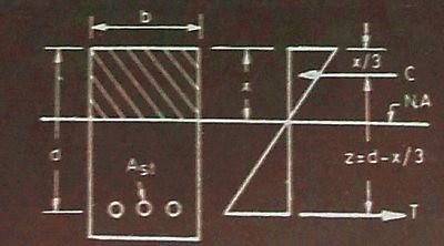
The moment of resistance of the concrete section is the moment of couple formed by the total tensile force (T) in the steel acting at the centre of gravity of reinforcement and the total compressive force (C) in the concrete acting at the centre of gravity (c.g.) of the compressive stress diagram. The moment of resistance is denoted by M.

The distance between the resultant compressive force (C) and tensile force (T) is called the lever arm, and is denoted by z.

Moment of resistance | Singly reinforced Section

From the diagram above, it is clear that the intensity of compressive stress varies from maximum at the top to zero at the neutral axis.

Therefore, centre of gravity of the compressive force is at a distance x/3 from the top edge of the section.

Therefore, z = d-x/3

Read more

Solved Numericals for Singly reinforced Sections | Design Method 2

Design of Singly reinforced Sections | Method 2

In our article series for Singly reinforced sections, we have covered the following:


Numerical Problem

Find the position of the neutral axis of a reinforced concrete beam 150mm wide and 400mm deep (effective). Area of tensile steel is 804mm2. (modular ratio = m = 18.66)

Step One:

Given that:

b = breadth of a rectangular beam = 150mm

d = effective depth of a beam = 400mm

Ast = cross-sectional area of steel in tension = 804mm2

x = depth of neutral axis below the compression edge

m = modular ratio = 18.66

Taking moments of area of compression and tension sides about neutral axis,

bx.x/2 = mAst (d – x)

Read more

Design of Singly reinforced sections | Design Method 2

Guide to design of Singly reinforced Sections

For “Singly reinforced sections” article series, we have covered the following:


Now we will move on with our discussion on “2nd Design method” for the design of Singly reinforced Sections.
We will follow a simple three-step procedure for the design of singly reinforced sections.

Step One:

Given that:

  • Dimensions of section (b and d)
  • Area of tensile steel (Ast)
  • Modular ratio (m)
Stress-strain diagram

From the figure above, we can see that the neutral axis is situated at the centre of gravity of a given section. Therefore, the moments of area on either side are equal.

Read more

Assumptions for Singly reinforced Sections | RCC Structures

Singly reinforced Sections | Design of RCC Structures

In our series of articles for singly reinforced sections, we have covered the following:

Now, we will move on with our discussion on “assumptions for singly reinforced sections”.

Stress-strain diagram
The equivalent stress-strain diagram is developed with respect to the mentioned assumptions in the post.
  1. The sections that are plane before bending remain plane after bending, at any cross-section.
  2. All tensile stresses are taken up by steel reinforcement and none by concrete.
  3. The stress to strain relationship of steel and concrete under working load is a straight line.
  4. The modular ratio m has the value 280/3σcbc
  5. There is a perfect adhesion between steel and concrete and no slip takes place between steel and concrete.

Understanding Stresses and Modular ratio | RCC Structures

Stresses in Steel and Concrete | Building Construction

In one of our previous articles, we discussed “Basic definitions and formulas”.

Now we will move on with our discussion on “Permissible stresses in concrete and steel” and “Understanding Modular ratio”.

Permissible Stresses in Concrete

Reinforced concrete designs make use of M15 grade concrete. The permissible stresses for different grades of concrete is different. They are given below:

Sr. No. Concrete Grade M15 M20 M25 M30
1. Stress in compression

  1. Bending


5 7 8.5 10
  1. Direct


4 5 6 8
2. Stress in bond (average) for plain bars 0.6 0.8 0.9 1.0
3. Characteristics compressive strength 15 20 25 30

 Also refer for other values in IS:456-1978

Permissible Stresses in Steel

The permissible stresses for different grades of steel are given in the table above.

The different grades steel available in the market with their market names are as follows:

Mild Steel

Grade I steel is known as mild steel. The abbreviation used for Mild steel is (m.s.)

High Tensile deformed steel has two types. They are as follows:

  1. Grade Fe415 (Tor-40 or Tistrong I)
  2. Grade Fe500 (Tor-50 or Tistrong II)

The names of the high tensile deformed steel have been derived from their manufacturers.

Read more

Moment Distribution Method | Civil Engineering

Step by Step procedure for Moment Distribution Method

Step One:

Initially all the members are assumed to be fixed. Calculation of fixed end moments is to be done.

Moment Distribution Method diagram

Step two:

Fixidity at the joint is released and the balancing moment at the joints is distributed to various members depending upon their thickness.

Step three:

A part of this moment is carried over to the other end of the member and the carry over moment is computed.

Read more

Bending Moment and Fixed Moment Calculations

Bending Moment and Shear Force diagrams

What is Bending Moment?

The element bends when a moment is applied to it. Every structural element has bending moment. Concept of bending moment is very important in the field of engineering especially Civil engineering and Mechanical Engineering.

Unit of measurement: Newton-metres (N-m) or pound-foot or foot-pound (ft.lb)

Bending moment is directly proportional to tensile and compressive stresses. Increase in tensile and compressive stresses results in the increase in the bending moment. These stresses also depend on the second moment of area of the cross section of the element.

What is Shear stress?

Shear stress is defined as the measure of force per unit area. Shear stress occurs in shear plane. There are many planes possible at any point in a structure which can be defined to measure stress.

Stress = Force/Unit area

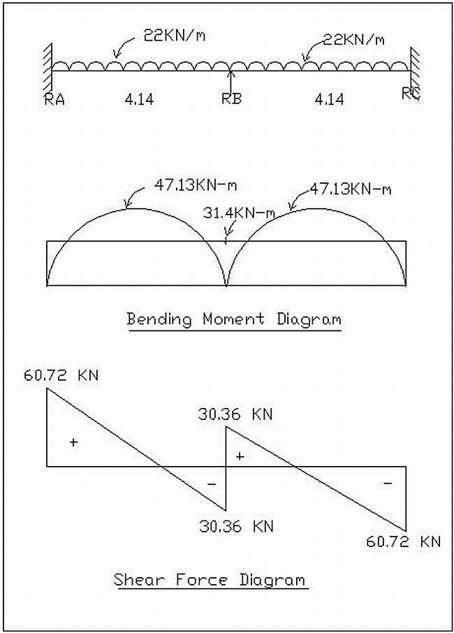
Example: Bending Moment and Shear Force Calculations

Frame diagrams | Bending moment and shear force calculations

Simply supported bending moment

Mab = wl2/8 = (22×4.14×4.14)/8

= 47.13 KN-m

Mbc = wl2/8 = (22×4.14×4.14)/8

= 47.13 KN-m

Read more

Building Materials | Use of Carbon-negative Cement in Building Construction

Carbon-negative cement | New revolutionary Building material

Carbon-negative cement…?? Sound different, doesn’t it?

Have you ever realized how much carbon is emitted because of using concrete in the construction of buildings, highways, dams, bridges etc?

Well, here’s an answer to that. It is found that out of the 100% carbon dioxide emissions, 5% of the emissions are caused by human activities. Majority of the carbon emission is caused by usage of concrete in the constructions. How? Cement is an indispensible ingredient used for making concrete. Cement is made by baking limestone and clay powders under intense temperatures (high temperature). The intense heat which is required for the production of cement is achieved by burning of fossil fuels which in turn release large amount of carbon dioxide into the atmosphere.

Building Construction | We can just imagine to what extent the carbon dioxide would be released into the atmosphere
Building Construction | We can just imagine to what extent the carbon dioxide would be released into the atmosphere.

Carbon dioxide is also released when the conversion of limestone takes place in the kilns. This conversion is called “Calcination”. It has been observed that the amount of carbon dioxide emitted during calcination is much higher than that which is released due to burning of fossil fuels.

Recently, a British company called “Novacem” came up with this concept of manufacturing ‘carbon-negative’ cement that absorbs more carbon-dioxide than it emits over its entire life cycle.

Read more