Bending Moment and Shear Force diagrams
What is Bending Moment?
The element bends when a moment is applied to it. Every structural element has bending moment. Concept of bending moment is very important in the field of engineering especially Civil engineering and Mechanical Engineering.
Unit of measurement: Newton-metres (N-m) or pound-foot or foot-pound (ft.lb)
Bending moment is directly proportional to tensile and compressive stresses. Increase in tensile and compressive stresses results in the increase in the bending moment. These stresses also depend on the second moment of area of the cross section of the element.
What is Shear stress?
Shear stress is defined as the measure of force per unit area. Shear stress occurs in shear plane. There are many planes possible at any point in a structure which can be defined to measure stress.
Stress = Force/Unit area
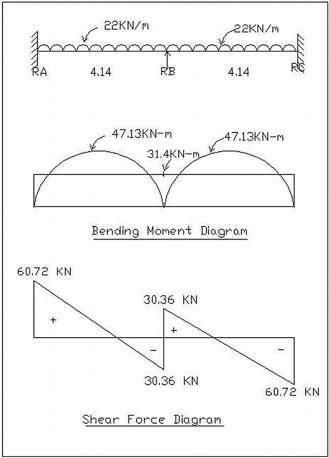
Example: Bending Moment and Shear Force Calculations

Simply supported bending moment
Mab = wl2/8 = (22×4.14×4.14)/8
= 47.13 KN-m
Mbc = wl2/8 = (22×4.14×4.14)/8
= 47.13 KN-m
Fixed Moments
Moment about B
wl2/12 = (22×4.14×4.14)/12
= 31.4 KN-m
Support reactions
RA+RB+RC = 2(22×4.14)
= 182.16 KN
3RA = 182.16
RA = 60.72KN
RA = RB = RC = 60.72 KN
Also check out: Introduction to Load Calculations
Please, I need assistance in the use of Moment distribution method for designing beams, slabs,etc. I don’t have a firm grip of the basics, kindly open my eyes to the nitty gritty… tnx
me a diploma engineer, interested in structural designing, It will be very helpful if you post a complete structural analysis and design of any G+2 framed structure including load calculation, bending moment, etc. thank you in advance
hw did we get the 30.36kn for the shear force diagram
i need bending moment diagram books