Guide to design of Singly reinforced Sections
For “Singly reinforced sections” article series, we have covered the following:
- Basic definitions and formulas
- Understanding stresses and modular ratios
- Assumptions for singly reinforced sections
- Design procedure for Singly reinforced section – I
- Solved Numericals for Singly reinforced beam | Method I
- Design of Singly reinforced sections | Design Method 2
- Solved Numericals for Singly reinforced beam | Method 2
- Moment of Resistance for Singly reinforced sections
- Solved numerical example | Moment of resistance
- Solved numerical example 2 | Guide to singly reinforced sections
Now we will move on with our discussion on “2nd Design method” for the design of Singly reinforced Sections.
We will follow a simple three-step procedure for the design of singly reinforced sections.
Step One:
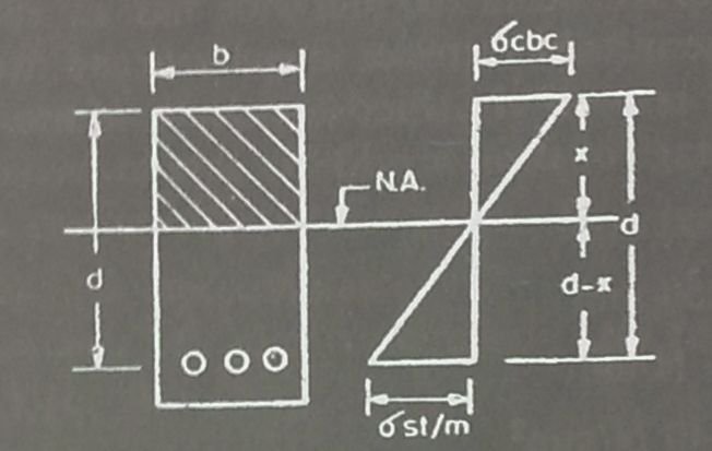
Given that:
- Dimensions of section (b and d)
- Area of tensile steel (Ast)
- Modular ratio (m)

From the figure above, we can see that the neutral axis is situated at the centre of gravity of a given section. Therefore, the moments of area on either side are equal.