Height of Collimation and Rise and Fall Method | Methods of Levelling

Methods of Levelling | Guide to Surveying and Levelling

In this article, we will discuss two important methods of Levelling. We will also study these Methods with the help of Numerical Examples in our successive articles.

There are two Methods of Levelling:

  1. Height of Collimation Method
  2. Rise and Fall Method

Height of Collimation Method

This method is simple and easy.

Reduction of levels is easy.

Visualization is not necessary regarding the nature of the ground.

There is no check for intermediate sight readings;

This method is generally used where more number of readings can be taken with less number of change points for constructional work and profile levellings.

Read more

Methods for Correcting the bearings affected by Local Attraction

Local Attraction | Methods for Correcting the bearings affected by Local Attraction

The deflection of a magnetic needle from its true position due to the presence of magnetic influencing material such as iron ore, magnetic rock, underground pipeline, electric cables, iron pipes, electric poles in its vicinity is called “Local Attraction”.

Methods of Correcting the bearings

There are two methods of correcting the bearings affected by local attraction:

  1. Included angle Method
  2. Error Computation

Included angle Method

In this method, the included angles of the traverse are calculated first, then starting from the line which is unaffected by local attraction and using the included angles, the corrected bearings of the traverse are computed.

Error Computation Method

In this method, the direction and the amount of local attraction at each survey station is determined.

Then starting from the line which is unaffected by local attraction, the corrected bearing of the traverse are computed.

This method is more accurate than the included angle method.

Hence it is adopted by most of the surveyors.

Read more

Types of Ranging | Chain Surveying

Methods of Ranging in Chain Surveying | Guide to Surveying and Levelling

In measuring a survey line, the chain has to be laid out on the ground between the stations.

If the line is short, the chain could be put in alignment easily but if it is long or the end station is not clearly visible, then intermediate points has to be established in line with end points to know the directions of the line by ranging.

Types of Ranging

There are two types of ranging:

  1. Direct ranging
  2. Indirect ranging

Direct ranging

Direct ranging is possible when the stations are intervisible.

Ranging is done by eye-judgement. Ranging rods are erected vertically beyond each end of survey line.

The surveyor stands 2m beyond the ranging rod while the assistant folds the ranging rod vertically in the intermediate stations.

The ranging rod is held roughly in line by the thumb and fore-finger.

The surveyor directs the assistant to move the rod to the left or right until the three ranging rods appear to be in a straight line.

To avoid errors due to the ranging rods not being vertical, the lower end of the rod are cited for alignment.

Read more

Chaining on Sloping Ground | Guide to Surveying and Levelling

Chaining on Sloping Ground | Surveying and Levelling

There are two methods for determining horizontal distance on sloping ground.

  1. Direct Method
  2. Indirect Method

Direct Method of Chain Surveying

This method is also known as “Stepping Method”.

The horizontal distances are directly measured by the process of stepping.

Procedure

A path of chain or tape is stretched out from ‘P’.

The path length of chain or tape depends on the steepness of the ground.

The follower holds the zero end of the chain at ‘P’ and directs the leader at P1 to be in the line of PQ and stretch the chain or tape above the ground in horizontal line.

Direct Method | Chain Surveying

The leader then transfers the point ‘P1’ to P2 on the ground by means of plumb bob or dropping a pebble or an arrow,

Now the followers take the new position ‘P2’ and directs the leader to move forward and stretch the tape or chain in a line of PQ.

Now the followers take the new position ‘P2’ and directs the leader to move forward and stretch the tape or chain in a line of PQ and the new position is P3.

Again the leader transfers the point P3 to P4 on the ground as done earlier.

This process is repeated till the point Q is reached.

Horizontal distance PQ = S1 + S2 + S3 + S4 + S5

Read more

Sources of Errors in Surveying | Civil Engineering

Sources of Errors in Surveying

In this article, we will discuss three major types of errors that are found to be very common in Surveying.

Types of Errors
Types of Errors

Types of Errors

  1. Instrumental errors
  2. Personal errors
  3. Natural errors

Instrumental errors

Error may arise due to imperfection or faulty adjustment of the instrument with which measurement is being taken.

For example:

A tape may be too long or an angle measuring instrument maybe out of adjustment. Such errors are known as Instrumental erros.

Read more

Types of Scales in Engineering Surveying

Types of Scales | Engineering Surveying

In the previous article, we discussed briefly on the topic of “Scales in Surveying” where we came across an important term “Representative factor” which forms an important part in understanding the scales in Surveying.

In this article, we will discuss different types of scales used in Surveying…

The scales are classified into four categories:

  1. Plain Scale
  2. Diagonal Scale
  3. Vernier Scale
  4. Scale of chords

Lets go on with the discussion of types of scales briefly for our better understanding…

Plain Scale

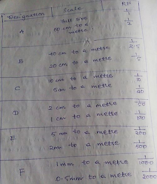
Plain Scale is one on which it is possible to measure two dimensions only. For example, measurements such as units and lengths, metres and decimetres etc.

Plain Scale
Plain Scale

Six different plain scales in metric used by engineers, Architects and Surveyors.

Diagonal Scale

On diagonal scale, it is possible to measure three dimensions such as metres, decimetres and centimetres, units , tens and hundreds; yards, feet and inches etc.

A short length is divided into number of parts using the principle of similar triangle in which sides are proportional.

Read more

Methods of Calculation of Areas in Surveying | Simpson’s Rule

Calculation of Areas in Surveying | Simpson’s Rule

In one of my previous articles, I discussed Midpoint Ordinate Rule and Average Ordinate Rule in detail with an example and listed out various important methods used for the calculation of areas in Surveying. In this article, we will deal with the next important method (rule) i.e. Simpson’s Rule along with a numerical example used for the calculation of areas in the field of Surveying.

Here are the five important rules (Methods) used for the calculation of areas in Surveying:

  1. Midpoint ordinate rule
  2. Average ordinate rule
  3. Simpson’s rule
  4. Trapezoidal rule
  5. Graphical rule

Simpson’s Rule

Statement

It states that, sum of first and last ordinates has to be done. Add twice the sum of remaining odd ordinates and four times the sum of remaining even ordinates. Multiply to this total sum by 1/3rd of the common distance between the ordinates which gives the required area.

Where O1, O2, O3, …. On are the lengths of the ordinates

d = common distance

n = number of divisions

Note:

This rule is applicable only if ordinates are odd, i.e. even number of divisions.

If the number of ordinates are even, the area of last division maybe calculated separated and added to the result obtained by applying Simpson’s rule to two remaining ordinates.

Read more

Contour Analysis | Guide to Surveying and Levelling

Importance of Contouring in the field of Surveying

Contouring is an imaginary line on the ground obtained by joining points having same elevation.

Characteristics of Contours

Contour lines are closed, however they may be close on the map itself or outside the map depending upon the topography.

The spacing between contour lines depends upon the slope of the ground.

In steep slopes, the spacing is small, for gentle slopes the spacing is large.

If the contour lines are equally spaced, they indicate uniform slope.

Contour Analysis
Contour Analysis

If the contour lines are parallel, straight or equally placed, they represent plane surface.

In a series of contour lines on the plan or map indicates either a hill or depression.

In case of the hill, the values of the elevation go on increasing towards the centre whereas in case of depression, the values go on decreasing towards the centre.

Read more

Duties of a Surveyor in the field of Surveying | Civil Engineering

Role of a Surveyor | Surveying and Levelling

Surveying is a subject that is studied by Civil Engineers as well as Architects. Some Civil Engineers take up Surveying as their profession but otherwise, there are surveyors who have the expertise in the field of surveying.

They have certain important duties as a Surveyor to be carried out. In this article, we will briefly discuss their division of work and their duties towards the field of Surveying.

The work of a surveyor can be divided into four parts:

  1. Field work
  2. Computing
  3. Mapping
  4. Setting

Field work

Making and recording measurements in the field.

Computing

Making the necessary calculations to determine areas, location, volume etc.

Read more

Tape Correction, Sag Correction and Pull Correction | Surveying and Levelling

Tape Correction, Sag Correction, Pull Correction and Temperature Correction

In this article, I will list out different formulas for the respective corrections…

Tape Correction

The following corrections are to be made for measurements taken with a tape because tape can never be practically used under specified standard conditions.

Correction for absolute length

Absolute length of tape is its actual length under specified condition

Ca = Lc/L

Where, Ca = correction to be applied to the tape in ‘m’

Lc = measured length in ‘m’

L = nominal length of tape in ‘m’

Correction for temperature

Length of tape is increased with the increase of temperature and decrease with decrease of temperature.

Ct = A (Tm – Ts)

Where,

A = coefficient of thermal expansion per one degree Kelvin

Tm = temperature during the measurement in Kelvin

Ts = temperature at which the tape standardised in Kelvin

Read more