Introduction to Design of RCC Structures

RCC structures

RCC (Reinforced Cement Concrete) is a construction technology which evolved with the evolution of different structural materials in the 18th century during the Industrial Revolution.

Industrial Revolution brought in new technology which helped in the manufacture of various materials. The Architect Le Corbusier used RCC for various constructions. He believed that any shape and form was possible; if RCC is to be used.

For example, Notre Dame Du Haut, Ronchamp, France

This is an example of Le Corbusier Project where he used RCC like plastic.

Notre Dame Du Haut, Ronchamp, France | RCC Structures

What is RCC?

RCC means Reinforced Cement Concrete, i.e., cement concrete reinforced with steel bars, steel plates, steel mesh etc to increase the tension withstanding capacity of the structure.

Cement Concrete can take up immense compression but weak in tension whereas steel is good in withstanding both tension and compression.
Read more

Use of Concrete Barriers

This is a guest post by Philip White

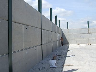
Concrete has been used for many years for providing a permanent or temporary barrier, or blockade in a variety of situations. One of the most common applications is for concrete barriers on the highway either in the centre of the road to divide opposite lanes of motorways, or for traffic diversion and channelling during work on the highways.

Read more

Guide to designing a Rolled Steel Beam

Six Step Guide to Designing a Rolled Steel Beam

Here are a few simple steps that are to be followed for the design of Rolled Steel Beam:

Step one

Calculate the maximum Bending Moment and Shear Force

Step two

Depending upon whether the beam is laterally restrained or unrestrained, calculate the permissible stress in bending compression (sigma bc) using the equation;

sigma bc = 0.66fy

Step three

Find the required Section Modulus (Zreq)

Zreq = M/sigma bc

Step four

From the structural tables, choose a suitable section such that the section modulus is slightly more than the required section modulus.

Step five

Check for shear.

Calculate the maximum Shear force in the beam. Calculate the average shear stress in the web and this should be less than 0.4fy.

Tv = (Shear Force)/HLw

where = H = height of the web

Lw = length of the web

Step six

Check for deflection

Ymax < 1/325 of span

Example of the Design of Shear reinforcement in a beam

Design of Shear reinforcement in a beam

A reinforced cement concrete beam 300mm wide and 500mm effective depth is subjected to a shear force of 40KN at the ends. The beam is provided with 6 bars of 20mm diameter of which 3 bars are cranked at 45 degrees. Design the shear reinforcement for M20 grade concrete.

Here are the steps for the design of Shear Reinforcement in a beam:

Width of the beam = b = 300mm

Shear force = Vu = 40KN

Effective depth = d = 500mm

Area of steel, Ast = 3 x 3.14/4 x 20 x 20 = 942.47 mm2

Step one

Nominal shear stress

Tv = Vu/bd

Tv = 40 x 1000/(300 x 500) = 0.26N/mm2

Read more

Guide to Design of Shear Reinforcement in a beam

Design of Shear Reinforcement in a beam

The beam is failed by the diagonal tension in which the cracks start from support and extend upto a distance equal to effective depth and making an angle more or less than 45 degrees.

Shear reinforcement diagram (beam longitudinal section)

Here are the steps for the design of Shear Reinforcement in a beam:

Step one

Nominal shear stress

Tv = Vu/bd

Where, Vu = shear force due to design load

b = width of the beam

d = depth of the beam

Step two

Percentage of steel

Percent steel = Ast/bd x 100

Read more

Differences between Working stress method and Limit state method

Design of RCC Structures

The design of the components of the RCC structure can be done in the following two ways:

  1. Working Stress Method
  2. Limit State Method
Methods of RCC Design

Here are some of the design procedures of the components of the RCC structures:

Design of RCC beams

Design of RCC columns

Design of RCC staircase

Design of Foundations

Design of Simply Supported Slabs

In this article, we are going to discuss the major difference between the two important methods of RCC design. This will help us understand the mechanics of the Structural Design and which method is to be adopted for better efficiency.

Read more

Testing for Hardened Concrete | Building Construction

In my earlier article, we discussed “Tests for Fresh Concrete” in detail which will reduce the probability of failure that a building undergoes after the concrete hardens. In this article, we are going to discuss the “Tests for Hardened Concrete in Detail”.

Main objective of tests is to ensure properties of concrete vis-a-vis control quality and to adhere to the specifications. Properties of concrete are a function of time and ambient humidity.

Tests for Hardened Concrete

Compression tests

Specimens used – Cube, cylinders and prisms.

Cube test

  • Tested normal (perpendicular) to the position of cart steel moulds of 150mm x 150mm x 150mm. Apply oil inside. Mould to be filled in 3 layers. Cone is filled to overflow and then it is compacted. Steel scale rule is used to chop off surplus (gives homogeneity)
  • Each layer is compacted with 35 strokes of 25 diameter steel squares pinner.
  • The specimen is stored for 24 hours at 18 to 22 degrees at relative humidity not less than 90%.
  • Mould is the removed and cured (simulating field conditions)
  • In compression test, cube is in contact with platens of the testing machine load is applied at constant rate of stern (15Mpa/minute)
  • Crushing strength is reported nearest to 0.5Mpa.

Read more

Remedial Measures to prevent failure of Concrete

Remedies adopted to prevent failure of Concrete

Prevention of failure of Concrete will help preventing the building from failure. Good quality concreting strengthens the building and keeps it standing. Failure of Concrete results in structural failure of the building. Therefore, to prevent this from happening, measures have to be taken in order to strengthen the building and prevent it from structural failure.

Remedial Measures to prevent failure of Concrete

Capping

It does not affect the strength adversely and reduces scatter compared with uncapped specimens.

Grinding

  • Very good, expensive, very satisfactory results; it is done using silicon carbide abrasion. Specimens give same strength as cast face results.
  • Ideal capping shall have stress-strain properties similar to concrete, so that no splitting can take place and to achieve uniform stress distribution, it shall be 1.5mm to 3mm thick. A strong capping can increase the strength of the specimen.
  • Influence of capping is higher on high and medium strength concretes.
  • Capping can be done with neat cement after 2 hours of casting (to allow for plastic shrinkage of concrete). Dental plaster also can be used for capping due to its early strength gain and smooth finish it is viscous too. Do not use plaster of paris due to its low strength.

Read more

Tests for Fresh Concrete | Building Construction

Tests for Concrete to be performed on site

Tests are held at 28 days, 7 days and 3 days. Constituent of mix should be such that concrete can be transported, placed and finished easily without segregation.

  • Workability – it is a property of fresh concrete and affects the finished product as it affects compaction.
  • Need for workability – Imparted by the amount of useful internal work necessary to provide full compaction.
Tests for Fresh Concrete

Optimum water varies for different methods of compaction

  • i.e., more water – hand compaction – lower density
  • less water – mechanized compaction – higher density

If we add more water, the workability may increase may increase but core has more voids

  • 5% of more voids – reduces strength by 30%
  • 2% of more voids – reduces strength by 10%

The voids result due to –

The entrapped air voids are caused by grading of fine aggregate.

Excess water evaporating later excess – (water) voids are due to increase in workability

Aim should be to have maximum density – therefore for maximum compaction, you will have to have optimum water cement ratio, at which both the type voids are at minimum.

Read more

Classification of Cracks | Treatment of Cracks in a Building

Importance of Classification of Cracks

Cracks in a building are like ailments in human body. The building gets weaker and weaker if the cracks are not treated properly. The cracks give an impression of faulty and poor quality work. Moisture penetrates through the cracks and deteriorates the external facade as well as the internal facade. For determining a treatment procedure for the cracks, cracks have to be classified depending on its cause and nature. Different types of cracks have to be treated in different ways depending on its nature of occurrence.

Cracks in Buildings
Cracks in Buildings

In my earlier articles, I have discussed major and minor causes of cracks. Studying these causes also help in the classification of cracks.

Minor causes of Cracks

Major causes of Cracks

The classification of cracks is based on various factors:

  1. Direction of the cracks
  2. Extent of the cracks
  3. Width of the cracks (if tapers)
  4. Width of the cracks
  5. Depth of the cracks
  6. Alignment of the cracks
  7. Sharpness of the edges
  8. Cleanliness
  9. General

Read more