Design of Doubly reinforced sections | Numerical example

7 step design procedure for Doubly reinforced sections

In our article series for “Design of Doubly reinforced sections”, we covered the following:

What are doubly reinforced sections?

Methods for determining Neutral Axis?

Solved numerical examples for determining Neutral Axis

Numerical examples for practice (Find Neutral axis)

Methods for calculating Moment of Resistance

Numerical example for calculating Moment of resistance

Types of problems in Doubly reinforced sections

6 step prodecure for determining stresses in steel and concrete 

Numerical example | Stresses in steel and concrete

7 step procedure for designing doubly reinforced sections

We shall now proceed with a numerical example “Design of Doubly reinforced sections” using the 7-step procedure we discussed in the previous article.

Numerical problem:

A doubly reinforced concrete beam 250mm wide and 600mm deep overall has to resist an external bending moment of 95kN-m. Find the amount of tensile and compressive steel required, if cover to the centre of steel on both sides is 50mm. σcbc = 5 N/mm2, σst = 140 N/mm2, m = 18.66

Given that:

Breadth of the beam = b = 250mm

Effective depth of the beam = d = 600 – 50 = 550mm

Distance of compressive steel from the top edge of the beam to the centre of the steel = d’ = 50mm

Permissible stress in concrete = σcbc = 5 N/mm2

Permissible stress in steel = σst = 140 N/mm2

Modular ratio = m = 18.66

Bending moment = M = 95 kN-m

Step one:

To find xc

σcbc/ (σst/m) = xc/(d – xc)

5/(140/18.66) = xc/(550 – xc)

xc = 219.95 =  220mm

Read more

Design procedure for designing doubly reinforced section

7 step procedure for “Design of Doubly reinforced sections”

In our article series for “Design of Doubly reinforced sections”, we covered the following:

What are doubly reinforced sections?

Methods for determining Neutral Axis?

Solved numerical examples for determining Neutral Axis

Numerical examples for practice (Find Neutral axis)

Methods for calculating Moment of Resistance

Numerical example for calculating Moment of resistance

Types of problems in Doubly reinforced sections

6 step prodecure for determining stresses in steel and concrete 

Numerical example | Stresses in steel and concrete

In our previous article, we discussed a detailed 6 step procedure for determining stresses in steel and concrete followed by a numerical example. Now we shall move on with the “design procedure for doubly reinforced sections”.

Generally the following data are given:

Breadth of the beam = b

Effective depth of the beam = d

Permissible stress in concrete = σcbc

Permissible stress in steel = σst

Modular ratio = m

Bending moment = M

To solve a problem, the following procedure may be followed.

Design the beam as a singly reinforced one (balanced section)

Step One:

Find xc by

σcbc/ (σst/m) = xc/(d – xc)

Read more

6 step procedure for determining stresses in steel and concrete | Doubly reinforced sections

Numerical example for determining stresses in steel and concrete

In our article series for “Design of Doubly reinforced sections”, we covered the following:

What are doubly reinforced sections?

Methods for determining Neutral Axis?

Solved numerical examples for determining Neutral Axis

Numerical examples for practice (Find Neutral axis)

Methods for calculating Moment of Resistance

Numerical example for calculating Moment of resistance

Types of problems in Doubly reinforced sections

Determining stresses in steel and concrete 

Numerical example | Stresses in steel and concrete

In our previous article, we discussed a detailed 6 step procedure for determining stresses in steel and concrete. Now we shall move on with a numerical example in which we will use the 6 step procedure to solve the problem.

Problem Type two: Determining stresses in steel and concrete using the 6 step procedure

A rectangular beam is 200mm wide and 480mm deep. It has to resist a bending moment of 100 kN-m. The reinforcedment consists of four 25mm ⏀ bars on tension side and three 22mm⏀bars on compression side. The centres of bars being 30mm from the top and bottom edges of the beam. Find the stresses set up in steel and concrete. m=18.66

Given data is as follows:

Breadth of the beam = b = 200mm

Effective depth of the beam = d = 480 – 30 = 450mm

Distance of compressive steel from the top edge of the beam to the centre of the steel = d’ = 30mm

Bending moment = M = 100kN-m

Modular ratio = m = 18.66

Area of tensile steel = Ast = 4 π/4 x 25 x 25 = 1964 mm2

Area of compressive steel = Asc = 4 π/4 x 22 x 22 = 1140 mm2

Step one:

Find x:

bx.x/2 + (1.5m – 1)Asc (x – d’) = mAst(d-x)

200x2/2 + (1.5×18.66 – 1) 1140 (x – 30)

= 18.66 x 1964 x (450 – x)

Therefore, x2 + 674.17x – 174147 = 0

Read more

Determining stresses in Steel and Concrete | Doubly reinforced Sections

Six step procedure for determining stresses in steel and concrete

In our article series for “Doubly reinforced Sections design guide”, we have covered the following:

What are doubly reinforced sections?

Methods for determining Neutral Axis?

Solved numerical examples for determining Neutral Axis

Numerical examples for practice (Find Neutral axis)

Methods for calculating Moment of Resistance

Numerical example for calculating Moment of resistance

Types of problems in Doubly reinforced sections

Determining stresses in steel and concrete 

Numerical example | Stresses in steel and concrete

Now we shall proceed with a simple 6 step procedure for determining compressive stresses in steel and concrete. Further in our next article, we shall also solve a numerical using the same method.

Generally, the following data is given for reference with the help of which we can determine the stresses in steel and concrete

Breadth of the beam = b

Effective depth of the beam = d

Area of tensile steel = Ast

Area of compressive steel = Asc

Modular raito = m

Bending moment = M

Six step procedure for determining the compressive stresses in steel and concrete:

Step One:

Find x by using the following formula:

bx.x/2 + (1.5m – 1)Asc (x – d’) = mAst(d-x)

Read more

Types of Problems | Design of Doubly Reinforced Sections

Stepwise procedure for calculating Moment of resistance and compressive stresses in steel and concrete

While we proceed with the article series for “Doubly reinforced sections”, I would like to categorize the problems into different types. This will make your understanding of the concept better and concrete. I recommend that you practice enough to be able to understand and confidently solve the problems. This will also help you in real time when you would get into practice.

In our article series for doubly reinforced sections, we have covered the following:

What are doubly reinforced sections?

Methods for determining Neutral Axis?

Solved numerical examples for determining Neutral Axis

Numerical examples for practice (Find Neutral axis)

Methods for calculating Moment of Resistance

Numerical example for calculating Moment of resistance

Types of problems in Doubly reinforced sections

Determining stresses in steel and concrete 

Numerical example | Stresses in steel and concrete

Also check out: “Singly reinforced Sections” article series.

So let’s begin with different types of problems for “Doubly reinforced sections”.

Problem type 1

To find Moment of resistance (Mr)

In a problem where we have to find Mr, specific data is given so that you could calculate the Moment of resistance. The following data will be given in the problem. I suggest that you make notes of the points below.

Breadth of the beam = b

Effective depth of the beam = d

Area of tensile steel = Ast

Area of compressive steel = Asc

Permissible stress in concrete = σcbc

Permissible stress in steel = σst

Modular ratio = m

Four – step procedure to solving the problem:

Step one:

Find xc by the following formula,

σcbc/ (σst/m) = xc/(d-xc)

Step two:

Find x using the following formula,

bxx/2 + (1.5m – 1)Asc (x – d’) = m Ast (d – x)

Read more

Numerical Examples | Moment of Resistance Calculations

Moment of Resistance calculations | Doubly reinforced sections

In our article series for “Doubly reinforced sections”, we have covered the following:

What are doubly reinforced sections?

Methods for determining Neutral Axis?

Solved numerical examples for determining Neutral Axis

Numerical examples for practice (Find Neutral axis)

Methods for calculating Moment of Resistance

Numerical example for calculating Moment of resistance

Types of problems in Doubly reinforced sections

Determining stresses in steel and concrete 

Numerical example | Stresses in steel and concrete

Now we shall move on with a solved example. This will help you understand the methods in a better way. I suggest that you do them yourselves too. Practice will help you make your concepts more concrete and clear.

Numerical Example:

An reinforced concrete 300mm x 600mm effective dimensions is provided with tensile and compressive reinforcement of 1256mm2 each. The compressive steel is placed 30mm from the top edge of the beam. If σcbc = 7N/mm2, σst = 190N/mm2 and m = 13.33, find the moment of resistance of beam by following two methods:

1)     Elastic theory method

2)     Steel beam theory method

Read more

Moment of Resistance | Doubly reinforced Sections

Methods for calculating Moment of resistance for Doubly reinforced beam

In our article series for “Doubly reinforced sections”, we have covered the following:

What are doubly reinforced sections?

Methods for determining Neutral Axis?

Solved numerical examples for determining Neutral Axis

Numerical examples for practice (Find Neutral axis)

Methods for calculating Moment of Resistance

Numerical example for calculating Moment of resistance

Types of problems in Doubly reinforced sections

Determining stresses in steel and concrete 

Numerical example | Stresses in steel and concrete

Also check out: “Singly reinforced Sections” article series.

Now, our next step would be to study different methods for calculating moment of resistance (MR).

Two methods for calculating Moment of Resistance

There are two methods for calculating the moment of resistance of doubly reinforced sections. They are as follows:

  1. Method 1 – Elastic theory
  2. Method 2 – Steel beam theory

Method 1

Method using Elastic theory

The moment of resistance is calculated by taking the moments of forces about the centre of gravity of the tensile steel.

Diagram for determining Moment of resistance

From the figure above, we get,

Mr = Moment of compressive force of concrete about tensile steel + Moment of equivalent concrete force of compression steel about tensile steel

= bx(σcbc/2)(d – x/3) + (1.5m – 1)Asc. σcbc (d – d’)

Where, (1.5m – 1)Asc is the equivalent concrete area of compression steel.

Read more

Neutral Axis – Solved Example | Doubly reinforced Sections

Guide to design of Doubly reinforced Beam

In our article series for “Doubly reinforced sections”, we have covered the following:

What are doubly reinforced sections?

Methods for determining Neutral Axis?

Solved numerical examples for determining Neutral Axis

Numerical examples for practice (Find Neutral axis)

Methods for calculating Moment of Resistance

Numerical example for calculating Moment of resistance

Types of problems in Doubly reinforced sections

Determining stresses in steel and concrete 

Numerical example | Stresses in steel and concrete

Now we shall move on with a solved example. This will help you understand the methods in a better way. I suggest that you do them yourselves too. Practice will help you make your concepts more concrete and clear.

Example:

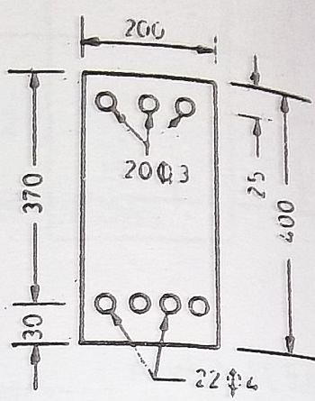
An reinforced concrete beam 200mm x 400mm overall is reinforced with 4 – 22mm⏀ bars with centres 30mm from the bottom edge and 3 – 20mm⏀ bars with centres 25mm from the top edge. Find the neutral axis of the beam, if m = 18.66

Doubly reinforced section diagram

Given that,

Width of the beam = 200mm

Effective depth of the beam = 400 – 30 = 370mm

Distance of compressive steel from the top edge of the beam to the centre of the steel = d’ = 25mm

Modular ratio = m = 18.66

Area of concrete = Asc = 3 x π/4 x (20)2 = 942 mm2

Area of tensile steel = Ast = 4 x π/4 x (22)2 = 1520 mm2

To find x:

Equating moment of area on compression and tension sides about N.A.

bxx/2 + (1.5m – 1)Asc(x – d’) = mAst (d – x)

200x2/2 + (1.5 x 18.66 – 1) 942 (x – 25)

= 18.66 x 1520 (370 – x)

Therefore, x2 + 537.87x – 111299 = 0

Solving the above equation, we get,

x = 159.579mm

Examples for practice

  • An reinforced concrete beam 300mm x 600mm overall is reinforced with 6 – 22mm⏀ bars with centres 30mm from the bottom edge and 5 – 20mm⏀ bars with centres 25mm from the top edge. Find the neutral axis of the beam, if m = 18.66
  • An reinforced concrete beam 300mm x 600mm overall is reinforced with 4 – 20mm⏀ bars with centres 25mm from the bottom edge and 6 – 20mm⏀ bars with centres 25mm from the top edge. Find the neutral axis of the beam, if m = 18.66

Guide to design of Doubly reinforced Sections | Civil Engineering

What are Doubly reinforced sections?

Sections that have tensile as well as compressive reinforcement are called doubly reinforced sections.

Necessity of design of doubly reinforced sections

When the dimensions of the beam are restricted for architectural or structural considerations, the section has insufficient area of concrete which results in inability of the beam to take sufficient compressive stresses. If not paid attention to, it could result in structural failure.

To solve this problem, steel is placed in the compressive area of the section to help the concrete section in resisting compressive stresses. (Steel is good at taking up both compression and tension.)

In this way, the moment of resistance of the section is increased without altering its dimensions.

Three important conditions where doubly reinforced sections are to be used:

1)       When the dimensions of the beam are restricted for architectural or structural purposes.

2)       Sections that are subjected to the reversal of bending moment (piles, braces in water towers etc.

3)       The portion of the beam over middle support in continuous T beams has to be designed as doubly reinforced section.

We are now going to begin with a series of articles on “Design of Doubly reinforced sections”. In our previous series of articles for “Singly reinforced sections“, we have covered every step in detail for the design and analysis of Singly reinforced sections.

We would be covering the following for “Doubly reinforced Sections”:

What are doubly reinforced sections?

Methods for determining Neutral Axis?

Solved numerical examples for determining Neutral Axis

Numerical examples for practice (Find Neutral axis)

Methods for calculating Moment of Resistance

Numerical example for calculating Moment of resistance

Types of problems in Doubly reinforced sections

Determining stresses in steel and concrete 

Numerical example | Stresses in steel and concrete

So let us begin with understanding the methods for determining the neutral axis for doubly reinforced sections.

Methods of determining Neutral axis for doubly reinforced sections

METHOD ONE:

Given that:

Dimensions of the beam:

b = width of the beam, d = depth of the beam

Permissible stresses in concrete = σcbc

Permissible stress in steel = σst

Modular ratio = m

From similar triangles in the equivalent concrete stress diagram,

σcbc/ (σst/m) = xc/(d – xc)

Read more

Green Electric Components | LED Lights | Research in lighting

Future of Lighting Industry

We are all acquainted with LED (light emitting diode). It is a semiconductor light source and was introduced as a practical electronic component in 1962. Earlier, LEDs emitted low-intensity red light but now the scenario has completely changed. We can now count LEDs under GREEN electronic component. They are tiny but efficient. Technology has made it possible in achieving efficiency with LED lighting.

LEDs (Light emitting diode)

LEDs pros and cons

Let us first look at it with a positive perspective.

LEDs are supposed to be the future of our lighting industry. They require low power for illumination. The power required for illumination is as low as required for a flashlight or the screen of our cellphone.

LEDs are very useful to light up smaller rooms. Bright white light can be achieved with minimum requirement of electric power. It has been used by the lighting designers. They can be very easily integrated with the false ceiling in any mall or showroom. Since, the requirement for the number of lights is larger in a showroom, LEDs are a very superior and an economical alternative since they are efficient and at the same time consume less electric power. I would say this is great way to embrace sustainability.

Now, let’s look at it with a perspective that will help us understand the shortcomings in LEDs technology. We will also discuss how researchers have found a perfect way to overcome these shortcomings.

Read more